Class E Solid State Tesla Coil
Description:
As an introduction to the world of solid state coiling, I have chosen to replicate Steve Ward’s class E tesla coil. The design was very simple, yet he seemed to have achieved good results, so I thought it would be a good first solid state coil.
Introduction:
I have always been intrigued by Tesla coils. Last summer I constructed a spark gap Tesla coil from some things I could find around my garage, and a neon sign transformer I got for about $20 at a local shop. While the it worked, the coil was much less than ideal.
The way SGTCs are built just seems very limiting, which made me want to try going solid state. Solid state Tesla coils are much more numerous in design, and the results you can get are just as numerous. There are huge diversities of spark length you can get, and plenty of designs to choose from. For a first attempt at solid state coiling I wanted something a little simpler than a half bridge. I felt Steve Ward’s class e coil was simple enough for my first attempt, so decided to build it.
I should probably explain a little bit about how Class E Tesla coils work. As you have probably heard before, Tesla coils are air cored resonant transformers. Which means when the primary circuit is oscillating at the resonant frequency of the secondary, voltages go through the roof. With spark gap Tesla coils, an LC circuit is setup with the primary to get it to oscillate at the resonant frequency of the secondary. With solid state coils, this oscillation is accomplished using electronics. The trouble is, the smaller the secondary is the higher the resonant frequency is, and with smaller coils, it can be rather difficult to use conventional driver topology to achieve the higher frequencies. To combat this, topology commonly used for radio applications is often utilized. This allows smaller coils to be driven effectively.
Design:
Above is the schematic of the coil, but you can also find it on Steve Ward’s website.
I guess the basic design already existed, but I decided I wanted to etch a board. I have never etched before and I thought it was about time I learned to. This circuit was simple enough that I felt comfortable trying it for my first etched board.
I drew up a schematic in eagle relatively easily. I did spend a while trying to untangle air wires on the board before I finally settled on a layout I could live with. I went with a double sided board (although in the future I think I will try to get my boards to be one sided)
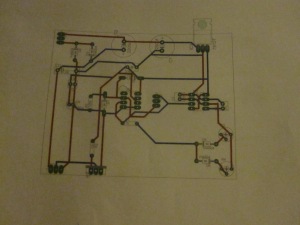
The above picture shows the basic layout. I did find one mistake on the board, and I think it is a problem with eagle’s autorouter. Pin 1 of the FET driver chip should have been grounded (and I did it in the schematic) but it wasn’t on the board. That is an easily correctable mistake though. If you want the Eagle file you can email me at Boson453@gmail.com.
Here is the printed layout. One of the layers is actually a mirror image so that it will be correctly lined up when placed face down on the board.
I plan to use toner transfer to make this board. The only problem is I don’t actually have a laser printer, So I will need to take the printed layout and get it copied onto photo paper somewhere. I’ll hopefully have a board etched by next week (It’s 7/14/13 now).
I should note that the diodes recomended in the schematic to clamp the antenna got lost (I forgot to order), so I used some point contact germanium diodes I had around. Although a 1N4148 would have worked fine, these are better suited for higher frequency applications, but mostly I think they look cool (the glass case makes them look like little vacuum tubes).
Construction:
July 19, 2013
A lot has happened. I should start from the beginning.
I had the board design as you can see above, but I do not have a laser printer. Since I planned on using toner transfer as the etching method, this was a problem. Luckily most office stores use laser printers in their copying machines so I just got the design copied onto photo paper with one.
My first attempt to transfer the toner ink failed. Luckily I had two copies made. I was much more successful the second time. After I removed the paper however, I found there were still several spots where there was quite a bit of ink missing. I tried to combat the issue by filling in the areas with sharpie. Just an FYI to anyone who may try this, it is not as reliable as you might think.
After etching the board (with ferric chloride of course) I have to say I am not terribly impressed with toner transfer. Admittedly some of the problems that came about are probably due to my lack of experience, but I still think I am going to try other methods in the future. Even so, I absolutely love etching. It for sure beats the hours spent putting something together on perfboard, and the additional hours afterwards spent finding and fixing mistakes.
Below is the board once populated.
To connect some of the off board parts/larger components, I put some pads on the board to connect to wires. The three in the top left are for the transformer (although only two are used) , the three in the bottom left are for connections to the primary, and the three next to the bottom left go to the mosfet.
Up to this point in this project, I had kind of forgotten the reason coilers are called coilers. I had up to this point put all my thought and effort into the electronics, and kind of forgot about the coil winding part. But of course it was inevitable that I would would wrap wire around a form for a couple hours. After all, it is a Tesla coil.
The coil was made from roughly 500 turns of 28 awg wire (8 inches tall) wrapped around a piece of 3 inch PVC (3.5 OD).
I threw together a little jig made from some books to assist in wrapping the coil. While it wasn’t the sturdiest, it served my purposes fine.
I was pretty happy with the end result, but it wasn’t quite finished. The coil had to be coated in several layers of polyurethane to prevent further turmoil down the road when temperature and humidity begin to change (winter is coming…). If this step is skipped the wire can expand and contract causing it to cross over itself and render the coil useless.
After varnishing, the coil doesn’t really look all that different, but it definitely is not coming unraveled any time soon.
the primary coil is still in the works. I got a 4 inch PVC coupler as the former for it and plan to wrap a few turns of 12 awg solid core wire around it. How many turns exactly is yet to be determined.
Now comes the fun part. Wiring everything together and seeing if it works. At first, it didn’t. One of my absolute least favorite things is working for a long time on a project and then turning it on for the first time only to have nothing happen.
Trouble shooting was made much easier because of the etched board, but it still took a while to figure out exactly what was going on. And to be honest I still am not quite sure of the cause of those countless anti-climactic moments proceeding the press of the power switch, but alas, I got it working.
What I do know is that there was one bad trace I didn’t catch before, and one of the capacitors had a too low voltage rating to perform its duty (it paid the ultimate price for this flaw). Also, stranded wire seems to do some weird things to the electronics, but that is mostly straightened out now.
While I did get first light, there is a lot of improving to do. First, you’ll notice there is a lot of breakout/corona discharge occurring along the wire to the main breakout point. I plan to shorten the wire and give a more permanent breakout point to help prevent losses in spark length. Second, it would be nice if this didn’t stay sprawled out over my table for much longer than it needs to be, so I will be making a frame to hold everything and make it more aesthetically pleasing, portable, and in general less likely to fall apart when touched.
July 23, 2013
I have been experimenting with how many turns to include on the primary. Steve Ward said a 1.2 turn primary worked best for him, but I found a little more, closer to 1.5 turns, worked best for me. I also played around with the coupling a little bit. It worked best about 1/3 up the secondary, but the primary former I bought wasn’t that tall, so I just moved the primary as high as I could without getting arcs to the secondary.
In the schematic you’ll notice there are two potentiometers (actually trimmers on the board) that control the on and off time of the signal from the 555 chip. Since 555’s output is connected to the enable pin on the gate driver chip, the its signal actually affects the characteristics and size of the arcs. Also, you can hear the frequency from the 555 as the coil operates since it is effectively turning the coil on and off. You could probably even get the coil to play music by tying the output of a microcontroller to the enable pin of the gate driver, but I didn’t really etch the board to allow for that addtion. Either way, I adjusted the 555 to get the longest arcs. this is a good way to adjust arc size and characteristic without actually tuning the coil.
Arcs to the secondary actually became a bigger problem than I thought. It happened several times when the primary was a little closer to the secondary or didn’t have the former between it and the secondary. Luckily none of the arcs burnt all the way through the insulation on the secondary, so it still works.
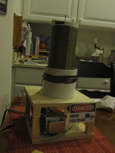
To make things look better, and to make the coil take up less space and be more portable I made a little frame to hold it. it is an 8″x8″x4″ box with open sides. the electronics are mounted to the top of the bottom face, and the primary and secondary were mounted to the top of the top face.
I also added a nail to act as a break out point. With just the wire sticking up, there were a lot of other breakout points that took away from the length of the main arc.
the two faces were made from 1/4″ plywood cut with a chop saw (I had to cut it from both sides), and the legs were made from four 4″ pieces of 1/2″x1/2″ wood (also cut with a chop saw). I mounted the board close to the back to with the trimmers on the edge to allow for adjustment if needed, and put the transformer in front of that. I made sure to put a fan on the front of the board to get circulation across the whole board which had a few other components (rectifiers, regulator and one of the capacitors) that were getting rather warm and either didn’t have, or had very small heat sinks. I added a danger sign just to add to the look, and then I was done.
Results:
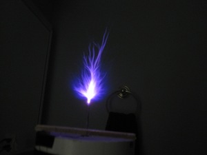
With optimum tuning and coupling, I managed to get arcs up to 4 inches (to a grounded piece of metal), which is pretty close to the 5 inches Steve Ward managed to get.

I also got a CFL bulb to light up from 1-2 feet away.
Aside from that, I managed to make a small coil that will be easy to take places for demonstrations if needed, and will be very quick (almost plug and play) to setup if I ever want to show anybody which is pretty nice.
Conclusion:
I managed to get good results from this coil despite it being my first solid state coiling project. It worked very reliably and is easy to adjust. (I also learned to etch circuit boards)
I am very happy with the outcome of this project, and I would say it would make an excellent first SS coiling project, or even first Tesla coil in general.


Hi ,,,
Could you tell me Wattage or ampere or power
you used for this TC please and thanks so much.
lam
It has about 50-70 watts on the input. Input xformer is 2A and about 35v DC although it is rated at 25v AC (peak to peak is about 41% greater than RMS).
Hi plz can u give me the eagle file on my this email fayezslim05@gmail.com plz