Van de Graaff Generator
About a year ago I attempted to build a Van de Graaff generator. Typically back then if I wanted to build something i would just gather what I could find for materials and then just wing it until I got something I could live with. for a lot of the things I made this ended up working okay, but it did not at all work for the VDG. There were numerous problems with belt tension, roller alignment, and motor power. After a while I simply gave up on the idea and moved on to other things.
Recently partially because of my work on my science fair project, I decided I was going to make a Van De Graaff Generator, but the right way this time. In the past any of my builds involving any kind of moving part hasn’t ended well, so I wasn’t too confident in my ability to successfully build anything mechanical going into this project. I had much more experience with designing, using tools, and putting things together in general this time, so as predicted the build went much more smoothly and was a pretty good success.
I designed the VDG to be built entirely from off the shelf parts since I have no way of machining anything myself. Luckily the VDG is very simple, so this task was pretty easy.
A VDG works by utilizing a difference in triboelectric properties between the two rollers, to get a charge on a rubber belt which carries charge to and from a metal sphere at the top where the charge can build to enormous amounts. The charge is transferred to and from the belt by two metal combs or brushes at the bottom of the and top of the belt.
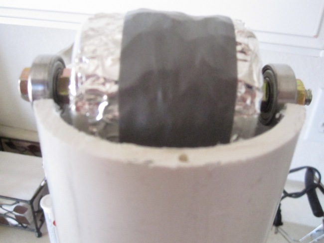
The first thing I made for the VDG was the rollers. I started out using some PVC end caps, but later changed the design to use bed rollers instead, because they were the perfect size and shape. To allow the rollers to spin in the VDG I attached skate bearings using a threaded rod and some nuts. I attached a pulley in a similar way to the bottom roller so It could be coupled to the motor later on.
The rollers have to be triboelectrically different, so I covered the bottom roller with Teflon tape, and the top roller with aluminium tape. Teflon and aluminum are at opposite ends of the triboelectric series, so this worked very well. The orientation of the rollers determines the polarity of the output, and with teflon on the bottom and aluminum on the top this VDG is negative.
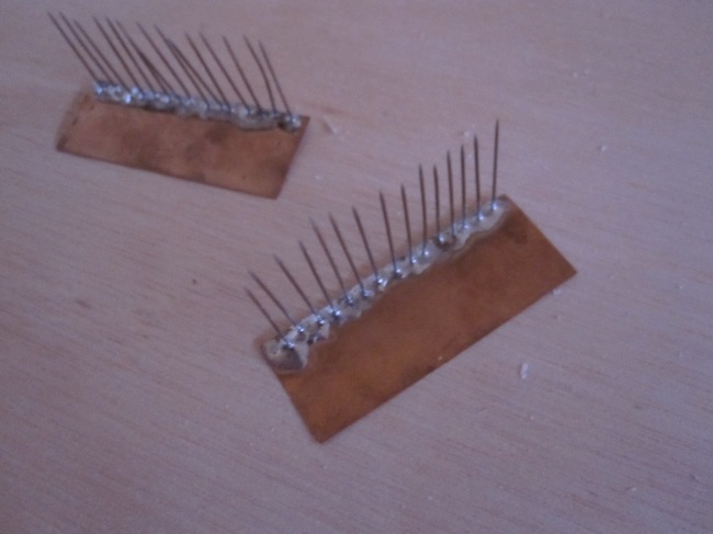
The next parts I made were the brushes. I made them by soldering straight pins on some sheet copper at regular 1/8 inch intervals. these brushes worked very well.
Next I had to make the body of the generator. For this I used a piece of three inch diameter PVC pipe. I needed the rollers to be separated by about 16 inches so the belt would be stretched to about 18 inches when installed. I settled on making three holes on the bottom, two for the roller, and one to help with the installation of the brushes. For the top I decided I would drill two holes for the roller, but then cut the PVC about halfway up these holes which would leave two arcs in the PVC for the roller to sit in, but would make the belt much easier to install. To hold the sphere on the top of the body I bent a coat hanger into a V shape and glued the two legs into two small holes I drilled in the top of the PVC. The sphere would get held up by the top of the wire V.
Next was the belt. I would have tried to make the belts myself if I could find any fitness bands that weren’t non-latex. In the end I just ordered a latex rubber VDG belt from Edmund Scientifics. Installing the belt was pretty straight forward. I had to do some disassembling of the bottom roller to get the bed roller part inside the PVC and the belt around it, but once I had that done I just had to pull it through the tube and put it around the top roller. The belt tension albeit not much, was enough to hold the top roller in place quite nicely.
To position the brushes, I nailed one brush to a small platform of scrap would and screwed into place under the bottom roller. the top roller was attached to the wire V I used to hold up the sphere.
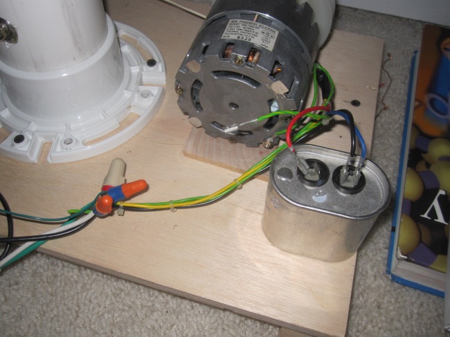
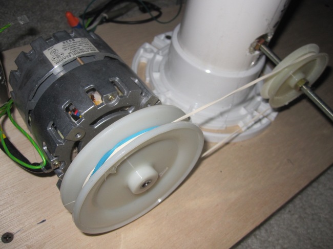
The last thing I had to do was assemble the drive system. I was originally going to use an old drill to power the generator, but decided to use a surplus AC motor instead. The AC motor worked very well. To step up the speed a little I decided to attach a large pulley to the motor and a smaller one to the bottom roller and use a belt to attach the two. \The ratio between the circumferences of the pulleys ended up being about 2:1 so the roller was spinning about twice as fast as the motor. This setup worked quite well.
To make the Sphere I used two stainless steel mixing bowls. I cut out the bottom of one with tinsnips, and taped the two together with electrical tape. I also Added electrical tape to all the sharp edges to reduce corona losses.
As of now The generator is putting out very strong arcs in the 4 inch to 6 inch range, but it can put out some weaker arcs that are a little over a foot long!
For more detailed instructions and a video visit instructables.com where I posted this project. You can search 350kv Van de Graaff Generator or copy this address: http://www.instructables.com/id/350kv-Van-de-Graaff-Generator/


Wow! In the end I got a webpage from where I can truly obtain
valuable facts regarding my study and knowledge.
Greetings! This is my first comment here so I just wanted to give a quick shout out and
tell you I genuinely enjoy reading your posts.
Can you recommend any other blogs/websites/forums that deal
with the same topics? Many thanks!
xellers.wordpress.com, wjscience.com, tcengineering.wordpress.com, adammunich.com, benkrasnow.bolgspot.com, uzzors2k.4hv.org, and a bunch more I am probably forgetting.